MSP430F5529LP Hardware Library: BUTTONS
Overview
The BUTTONS hardware library provides a button service framework that scans a pin (presumably connected to a button, although it can be any input signal), and executes a callback function when a button event is detected. Button events include single-click, double-click, or long-press events. The application registers the pins to scan including their polarity and callback functions. The button service framework is configured by the application during initialization to customize the debouncing and button event detection behavior.
Contains
- MSP430F5529LP_BUTTONS.h (optional)
- MSP430F5529LP_BUTTONS.c (optional)
These files are optional. They only need to be included if the BUTTONS library functionality is desired.
Requires
If the BUTTONS hardware library is included in a project, the following files are also required.
- MSP430F5529LP_TIMERA2.h
- MSP430F5529LP_TIMERA2.c
- MSP430F5529LP_GPIO.h
- MSP430F5529LP_GPIO.c
|
|
Public Definitions
|
#define MSP430F5529LP_BUTTON1     30
#define MSP430F5529LP_BUTTON2     22
|
There are two user-configurable buttons provided on the MSP430F5529LP launch pad board. Button 1 is connected to port pin P2.1, which is also package pin 30. Button 2 is connected to port pin P1.1, which is also package pin 22. These public definitions provide an easy way to assign the pin designation for these buttons during pin registration. NOTE: The pin registration for the button service framework uses the arduino-like pin designation. (see the GPIO hardware library for more information). |
typedef
    void (*ButtonCallback_t) (void);
|
This definition is required for the compiler to recognize the data type of ButtonCallback_t used as a function parameter in Set_Button_Callback as a function pointer. This has no other purpose. |
typedef volatile union
    {
    uint16_t reg;
    struct
    {
        uint16_t    single_press    :1;
        uint16_t    double_click    :1;
        uint16_t    long_press      :1;
    };
}ButtonEvents_t;
|
This is the Button Events data type. This definition is required by the application to interpret the return type of the Get_Button_Status function. The application can use the register access (myVar.reg) to determine if any type of event has occurred. This is useful if the type of button event is not important. Alternatively, the bit-select access methods can be used to detect the specific type of button event (myVar.single_press, myVar.double_click, myVar.long_press). In these examples, myVar is of type ButtonEvents_t. |
Public Functions
|
void
    MSP430F5529LP_BUTTONS_Initialize(
        uint16_t  ButtonSrvcInterval_ms,
        uint16_t  ButtonDbncThresh_cnt,
        uint16_t  ButtonDblClickTimeout_ms,
        uint16_t  ButtonLngPressTimeout_ms);
|
Calling this function initializes the Button Service Framework. The value ButtonSrvcInterval_ms defines how often the TIMERA2 1 ms interrupt will call the button service framework. For example, a value of 8 would result in the framework being called every 8th time the 1 ms timer fires, or every 8 ms. The value ButtonDbncThresh_cnt defines how many times a "new" button value must be debounced before the framework considers the new condition to be true. This results in a total debounce time equal to (service interval * debounce threshold). For example, if ButtonSrvcInterval_ms = 8, and ButtonDbncThresh_cnt = 3, the "new" button state would have to be true for 24 ms to be considered debounced. The value ButtonDblClickTimeout_ms defines the time that a push and release occurrence must fall within to be eligible for a double-click event. If two consecutive push and release occurrences each meet this criteria, then a double-click event will be triggered. The value ButtonLngPressTimeout_ms defines the time where a push and hold occurrence will trigger a long-press event. The following values are recommended for a good balance between responsiveness and robustness.
MSP430F5529LP_BUTTONS_Initialize(8, 3, 100, 500); |
void
    Set_Button_Callback(
        uint16_t index,
        uint16_t pin,
        uint16_t polarity,
        ButtonCallback_t callback);
|
Calling this function results in the registration of the specified pin at the array index specified. Pin numbers are registered using the package pin number (see GPIO library for more information). The number of pins that can be registered is defined by MAX_BUTTONS in the MSP430F5529LP_BUTTONS.c file. The default value is 10. If more pins are required to be registered this number can be increased. It is recommended however that it only be increased as needed, as each index, used or unused, allocates enough memory to hold a Button_Callback_t data structure. The legal index values are from 0 to MAX_BUTTONS-1, or in the default case: 0, 1, 2, and so on, up to 9. The Polarity value defines the "asserted" value for the signal being registered. For a button, this represents the "pushed" signal value. The callback value is the address of the function to be called when a button event occurs. The address of the function is passed by using only the function name, without parenthesis "()". If illegal values are passed to the function (i.e. illegal index, invalid pin number, polarity other than 0 or 1, or a NULL function pointer) no action is taken. If an index value is re-registered, the original registration is overwritten.
IMPORTANT: Index values used for registration must be consecutive values starting with 0. In order to limit the processing of unused index values, pin processing will stop after encountering the first unregistered index. |
ButtonEvents_t
    Get_Button_Status(
        uint16_t index);
|
Calling this function returns the button status for the pin registered at the index specified. If an illegal index is provided, a value of 0xFF will be returned. |
void
    Clear_Button_Status(
        uint16_t index);
|
Calling this function clears the button status for the pin registered at the index specified. If an illegal index is provided, no action is taken. |
CAUTION: It is recommended that calls to Get_Button_Status and Clear_Button_Status be done within the callback function. The callback function executes within the context of an ISR, meaning that interrupts are disabled and the button service framework is temporarily halted, which ensures that the button status is not being updated. If these functions are used outside of the callback function, they must be protected by disabling interrupts, otherwise a button event could occur between a read and a clear, and that event would be lost.
Example Code
The following example code is provided to demonstrate the functionality of this library. All examples are presented as main.c files, which are available on GitHub. In order to build the example projects, follow the instructions here for how to create and configure a new project.
| Example |
Summary Description |
|
Toggle the LEDs Using the Buttons
|
This example uses the BUTTON hardware library to toggle the LEDs when the button next to the LED is pressed. This demonstrates how to register a button, detect a button event, and take action based on the event. This is a very simple example that does not distinguish between the different kind of events, only that an event occurred.
Requires: Only the MSP430F529LP development board.
|
|
Display Button Events to an LCD Display
|
This example uses the LCD_HD44780_4BIT accessory to display the accumulated number of button events on a 20x4 LCD character display. This example demonstrates how to register a button, detect a button event, and decode the type of event that occurred. This example demonstrates how to detect single_press, double_click, and long_press events.
Requires: A 20x4 character LCD display based on the HD44780 controller and the LCD_HD44780_4BIT accessory library files.
|
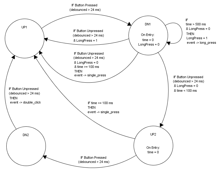
Button Service State Machine
A representative diagram of the button service state machine is provided below. The times specified in the diagram are based on initialization using the following values.
MSP430F5529LP_BUTTONS_Initialize(8, 3, 100, 500);
.